
Why the Shredder Feed System Decides Your Real Throughput
Buyers often compare motor power and rotor speed when choosing a metal shredder, yet the shredder feed system decides whether rated capacity is actually reached in daily production. A shredder starved of material runs below its rated load, while a shredder flooded with scrap jams, trips breakers, and wears cutting tools unevenly. Under unstable feeding, rated capacity exists only on the nameplate; under stable feeding, the same machine can run near rated load shift after shift, with more uniform output particle size.
Mixed scrap is unpredictable. Light-gauge sheet steel, aluminum profiles, and cable tangles behave differently inside the same hopper, and the shredder feed system must handle all three without operator intervention at the loading point. The paragraphs below explain the two most common feeding failures and how equipment design addresses each one.
Bridge-Blocking: The Most Expensive Feeding Failure
Bridge-blocking occurs when long, springy scrap such as coiled cable, aluminum extrusions, or thin sheet offcuts locks together across the hopper walls. Material stops falling, the rotors run empty, and an operator has to break the bridge manually. A well-designed shredder feed system prevents bridging with three features: steep hopper walls, an inclined chamber with no horizontal ledges where material can catch, and a forced-feed element that pushes material down into the cutting zone. The required wall angle depends on the friction angle of the specific scrap mix, so ask the supplier for the exact hopper wall angle of the machine model under discussion rather than assuming a catalog value.
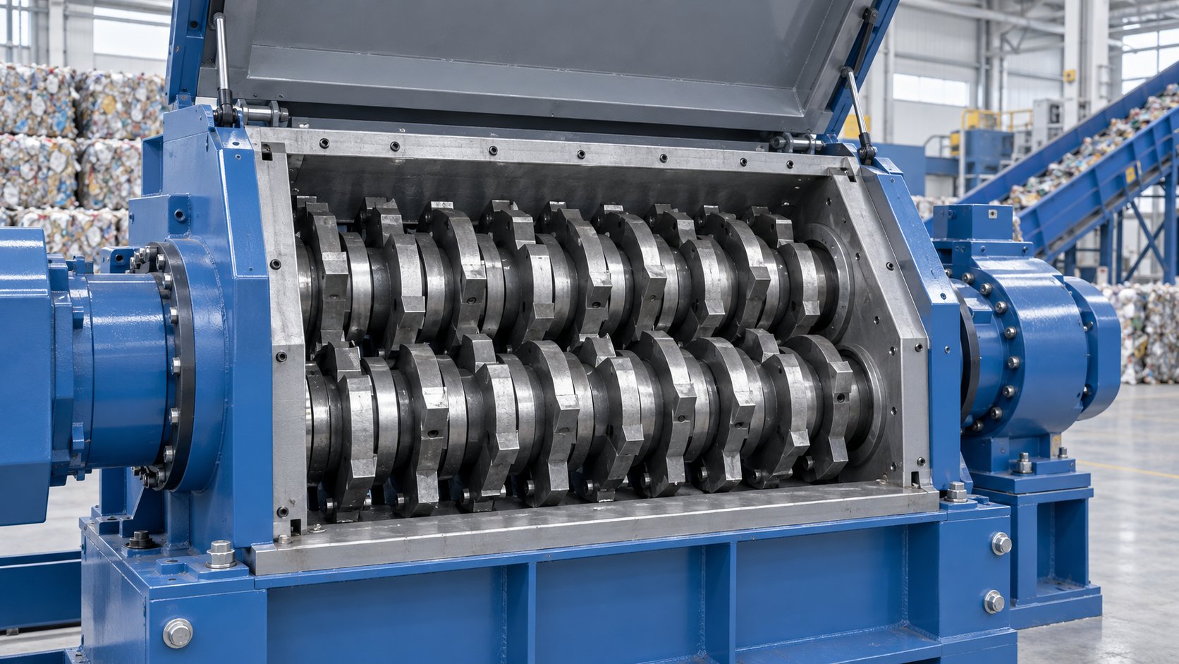
Machine architecture matters here. The TG-SingleShaft 200 Single-Shaft Metal Shredder uses a hydraulic feed ram above the rotor. In mechanical terms, the ram presses floating or tangled scrap continuously toward the bolt-on tool steel knives, so the cutting chamber receives a metered material column even when the scrap would otherwise bridge in a gravity-fed hopper.
Overload: When Feeding Outruns the Cutting Chamber
The opposite failure is overload. Front-loader operators rushing to clear a yard can push more scrap into the hopper than the cutting chamber can reduce, and the drive current climbs until the PLC trips the motor. Repeated overload trips waste production time and shock-load the gearbox. A controlled shredder feed system meters material instead of dumping it, keeping motor load inside the design band.
Auto-reverse logic adds a second layer of protection. When the control system detects a current spike, shafts reverse briefly to release trapped material, then resume cutting. Buyers comparing models should ask how the shredder feed system coordinates with this auto-reverse behavior, because a ram that keeps pushing during a reversal simply re-creates the jam.
Matching Feed Design to Your Scrap Mix
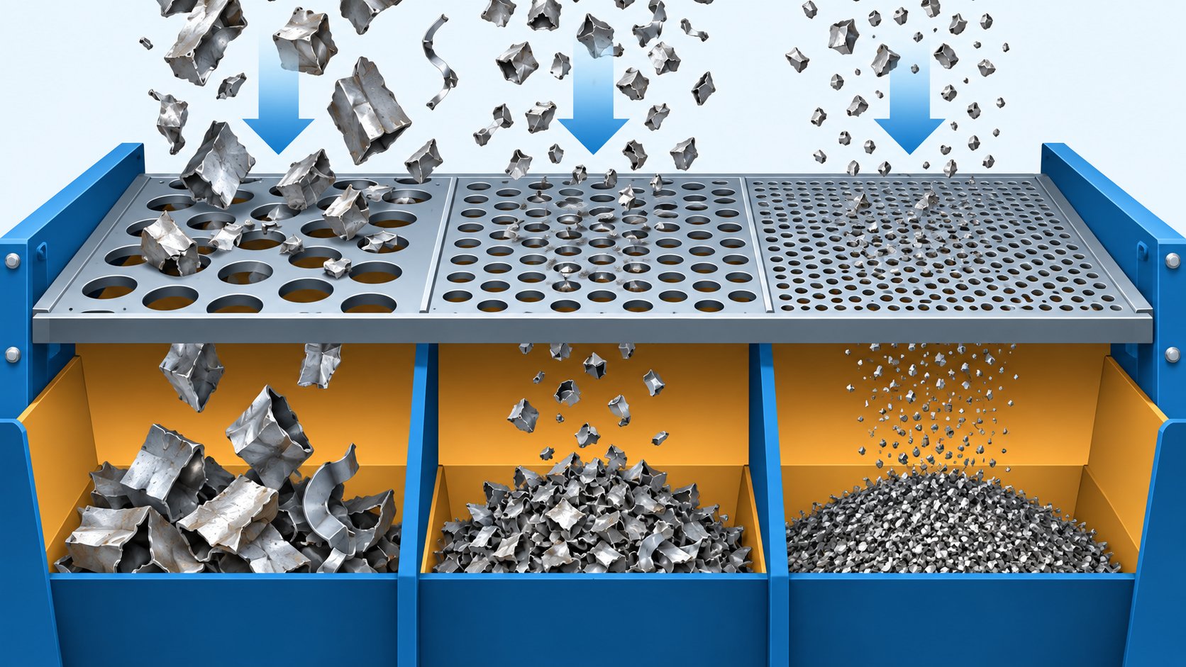
No single feeding arrangement suits every scrap stream, so match the shredder feed system to the dominant material. Dense, free-flowing ferrous scrap such as crushed car bodies and thick steel sections feeds reliably by gravity and conveyor. Light, bulky, or springy scrap needs positive displacement. Screen-controlled machines occupy a middle ground: the TG-FourShaft 400 Four-Shaft Metal Shredder combines a screen basket with its shaft configuration, so controlled discharge sizing pairs naturally with a metered infeed.
Before ordering, audit three numbers from your own operation: the largest single piece in the scrap mix, the bulk density of the lightest fraction, and the peak hourly volume your yard must clear. Each number maps to a specific machine parameter: the largest piece sets the minimum feed opening, the bulk density of the light fraction determines hopper volume and whether a forced-feed ram is required, and the peak hourly volume sizes the drive and discharge screen. Ask the supplier to confirm these three parameters in writing against the figures the yard measured.
Practical Checklist for Buyer Discussions
- Confirm hopper wall angles and the presence of a hydraulic feed ram for light or tangled scrap.
- Ask how the feed ram, main drive, and auto-reverse function are coordinated in the PLC program.
- Request reference throughput figures for material similar to your own scrap mix, not only for mixed heavy scrap.
- Verify screen options and discharge sizing so the shredder feed system and output specification are matched as one system.
Discuss Your Scrap Mix with Tiangong
Tiangong engineers review feeding problems against real material data. Send the three audited figures above, the dominant scrap types, and the target particle size through the site inquiry form, and the engineering team will confirm the feed opening, hopper configuration, and drive sizing that fit the measured scrap stream.
A metal shredder is only as productive as the material column above its rotors. Specifying the shredder feed system with the same seriousness as motor power and cutting chamber design is the difference between rated capacity on paper and rated capacity in production.