Shredder Components and Materials
Industrial shredders are made of six load-bearing assemblies: the cutter shaft, the alloy cutting discs bolted onto it, the reduction gearbox, the hydraulic system, the steel frame and chamber, and the PLC control cabinet. The external sheet metal hides all of them, which is why buyers evaluating durability usually need to look past the enclosure and ask what each assembly is made from, how it is fastened, and which parts are designed to be replaced individually.
Key takeaways
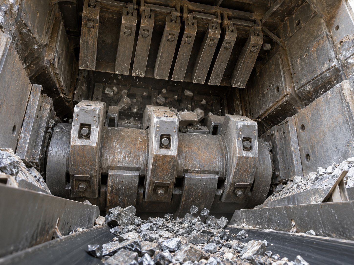
- The cutting interface is a shaft-and-disc system: a hardfaced shaft carries bolted alloy discs that can be replaced one at a time.
- Two hexagonal shafts counter-rotate, so material is sheared rather than simply pressed.
- Gearbox, hydraulic system and hardfaced shafts are produced in-house or sourced domestically, alongside in-house machining, welding and electrical assembly.
- Wear parts, not the frame, dominate long-term maintenance cost.
What this article covers
- Cutting shaft and disc materials
- Drive: gearbox and motors
- Hydraulics and chamber opening
- Frame, chamber and wear protection
- Control system and load monitoring
- Which parts wear and how they are replaced
- Material-to-application examples
The cutting interface: hardfaced shaft and bolted alloy discs
The cutter shaft is the part that defines how a shredder behaves under load. On twin-shaft machines the shaft profile carries the discs that actually grip and tear the feed material, and the shaft itself is hardfaced in the wear zones. Hardfacing is a welded overlay that rebuilds the surface where abrasive scrap runs against the shaft; it is a wear-management measure, not a coating that makes the shaft immune to wear.
The discs are alloy and are bolted to the shaft rather than cast as one piece with it. Two practical consequences follow:
- A damaged or worn disc can be exchanged as a single item, without scrapping the whole shaft assembly.
- Disc spacing and profile can be configured for the feed material, because the discs are separate components mounted on a common shaft.
On the TG-TwinShred 300, which runs two 45 kW drives and an 800 x 600 mm chamber, the cutting interface uses bolted alloy discs of this type. That machine is a reasonable reference point for the disc-bolt design philosophy at the smaller end of the range.
Hexagonal shafts and counter-rotation
The two shafts are hexagonal in section and rotate in opposite directions. Counter-rotation is what produces the shearing action: material passing between the shafts is caught by the advancing edges from both sides rather than being pushed along in one direction. The hexagonal section gives the discs a positive, keyed seat on the shaft, so drive torque is transmitted through the shaft profile as well as the bolt fixing.
Because the shafts counter-rotate, the load is shared across two drive trains, and the hydraulic or mechanical reversing function has to be able to clear a jam by backing material out of the cut. That is a design relationship, not a performance guarantee — actual throughput depends on feed material, disc configuration and drive sizing for the specific job.
Drive train: gearbox and motors
Behind each shaft sits a reduction gearbox that converts motor speed into the high torque, low-speed rotation a shredder needs. Gearboxes are one of the three assemblies this manufacturer produces in-house or sources domestically, along with hardfaced shafts and hydraulic systems. That matters to buyers for two reasons: gearbox condition is a common cause of unplanned downtime, and local sourcing usually shortens the path to a replacement unit or spare parts.
Motor rating scales with chamber size and target throughput. The range shows the span clearly:
| Model | Drive power | Chamber | Cutting interface note |
|---|---|---|---|
| TG-TwinShred 300 | 2 x 45 kW | 800 x 600 mm | Bolted alloy discs |
| TG-MegaShred 1600 | 2 x 400 kW | 1,400 x 1,100 mm | Thicker bolted discs, individually replaceable; load monitoring per shaft |
| TG-Hammer 800 | 750 kW | 500 t hydraulic compression | Reversible manganese steel hammers |
The TG-Hammer 800 is a different machine class: it uses reversible manganese steel hammers and hydraulic compression rather than a twin-shaft disc stack, so its wear parts and maintenance logic should not be read across to the twin-shaft models.
Hydraulic system and chamber opening
Hydraulics do two distinct jobs on a shredder. The first is driving functions such as ram or compression movement where the machine is equipped for it. The second is opening the chamber for maintenance. On the TG-MegaShred 1600, the chamber opens hydraulically and splits, which gives access to the cutting chamber without dismantling the surrounding structure — a direct labor consideration when discs are being changed.
Because hydraulic systems are assembled in-house or sourced domestically, hoses, cylinders, valves and the power unit can be matched to the machine rather than adapted from a third-party package.
Frame, chamber and wear protection
The frame and chamber are fabricated from steel plate. A shredder frame is not a wear part in normal operation, but it is the reference for shaft alignment and for the clearances around the cutting chamber, so the fabrication quality of the frame — welded, machined, then assembled — sets the baseline for everything bolted into it. Welding, machining and electrical assembly are all carried out in the manufacturer's own 12,000 m² factory, which is the same site where the hardfaced shafts, gearboxes and hydraulic systems are prepared or sourced.
Wear protection inside the chamber follows the same logic as the hardfaced shaft: the areas that see abrasive contact are treated or made replaceable, while the structural steel is not.
Control system, load monitoring and automatic reverse
The PLC cabinet holds the control logic, the drive interfaces and the protection functions. On this range, the control system includes automatic reverse — when the shafts encounter a load they cannot shear through, the control reverses rotation to clear the obstruction instead of stalling the drive.
The TG-MegaShred 1600 adds load monitoring on each shaft. Monitoring per shaft rather than per machine lets the control respond to an imbalance between the two sides, which is a common situation when feed material is unevenly distributed across a wide chamber. As with any control feature, its value depends on how the thresholds are set for the actual feed stream.
Which parts actually wear, and how they are replaced
Buyers asking what a shredder is made of are usually really asking which parts they will be buying again. The table below separates structural components from consumables:
| Component | Material / form | Wear behaviour | Replacement approach |
|---|---|---|---|
| Cutter shaft | Steel shaft, hardfaced wear zones | Surface wear in abrasive contact zones | Wear zones can be rebuilt by hardfacing |
| Cutting discs (twin-shaft) | Alloy discs, bolted | Edge and face wear | Individually replaceable on the bolted design |
| Gearbox | Reduction gearbox, in-house or domestic | Not a wear part; a reliability item | Replaced or serviced as an assembly |
| Hydraulic system | Cylinders, valves, power unit | Seals and hoses age | Component-level service |
| Frame and chamber | Welded steel plate | Structural; not normally consumed | Not a routine replacement item |
| Hammers (TG-Hammer 800) | Reversible manganese steel | Impact wear at the tip | Hammers are reversible; replace when both edges are spent |
The bolted-disc design is the single biggest factor in ongoing cost for twin-shaft machines, because it removes the need to replace a complete shaft-and-disc assembly when a limited number of discs are worn. On the TG-MegaShred 1600 the discs are both thicker and individually replaceable, and the hydraulic split chamber makes them accessible.
Matching materials to the application
The same machine built from the same components behaves differently depending on what is fed into it. Two examples show the range:
- A scrap operation feeding mixed light metal into a TG-TwinShred 300 is dealing mainly with edge wear on alloy discs and periodic hardfacing of the shaft zones.
- A heavy operation feeding bulky, dense metal into a TG-MegaShred 1600 is dealing with thicker disc wear, per-shaft load imbalance, and chamber access time during disc changes.
In both cases, the questions to put to a supplier are the same: what are the discs made of, are they individually replaceable, is the shaft hardfaced in the wear zones, and how is the chamber opened for maintenance.
Quality documentation and warranty
Machines in this range are supplied with CE marking and are built under ISO 9001 quality management, with a 12-month warranty. Standard models are quoted at delivery within 45 days. For a specific project, confirm the documentation package and the applicable model configuration with the supplier before ordering.
FAQ
Are the cutting discs cast into the shaft or bolted on?
They are bolted on. The bolted design allows a single worn or damaged disc to be replaced without replacing the shaft.
What does “hardfaced shaft” mean in practice?
The wear zones of the shaft carry a welded hardfacing overlay. It is a wear-management treatment applied to the areas that see abrasive contact, not a coating over the whole shaft.
Which shredder parts should a buyer stock as spares?
The consumables are the cutting discs and, on hammer machines, the hammers. Gearboxes and hydraulic components are reliability items rather than fast-wearing parts. The right spare holding depends on feed material and operating hours, and is worth agreeing with the supplier at the time of order.
Does every model have a hydraulic chamber opening?
No. The hydraulic split chamber opening is a feature of the TG-MegaShred 1600. Buyers should confirm the maintenance access arrangement for the specific model they are considering.
Next step
If you are comparing shredder designs on maintenance cost rather than purchase price, the specifications that matter are the disc material and fixing method, whether the shaft is hardfaced, how the chamber opens, and whether the drive is monitored per shaft. Send the feed material, expected throughput and chamber size you need, and the supplier can confirm which model configuration fits and what the wear-part replacement path looks like.